Tarea 4
Author:
Edi Calderon
Last Updated:
před 12 lety
License:
Creative Commons CC BY 4.0
Abstract:
About VIR

\begin
Discover why over 25 million people worldwide trust Overleaf with their work.

\begin
Discover why over 25 million people worldwide trust Overleaf with their work.
\documentclass[journal]{IEEEtran}%
%
%Paquete de Idioma
\usepackage[spanish]{babel}
%
%Codificación Alfabeto
\usepackage[utf8]{inputenc}
%
%Codificación de Fuente
\usepackage[T1]{fontenc}
%
%Índice
\usepackage{makeidx}
%
%Gráficos
\usepackage{graphicx}
\usepackage{subfig}
%\usepackage{xcolor}
%
%Matemática
\usepackage{amsmath}
\usepackage{amsfonts}
\usepackage{amssymb}
%\usepackage{amstext}
%
%Estilo de Página Numeración superior
%\pagestyle{headings}
%
%Hiperlinks \href{url}{text}
\usepackage[pdftex]{hyperref}
%
%Graficos y tablas
\usepackage{multirow}
\usepackage{multicol}
\usepackage{float}
\usepackage{booktabs}
%
\decimalpoint
%\bibliographystyle{IEEEtran}
%\bibliography{IEEEabrv,mybibfile}
%
%
\begin{document}
\renewcommand{\tablename}{Tabla}

%Titulo
\title{Tarea 4}

\author{\small{\textit{Universidad de San Carlos, Facultad de Ingeniería, Departamento de Física, Laboratorio de Física II}\\
\textit{201213418, Edi Cristofer Calderón González}}}%

\maketitle{}

\section{Circuito simple}

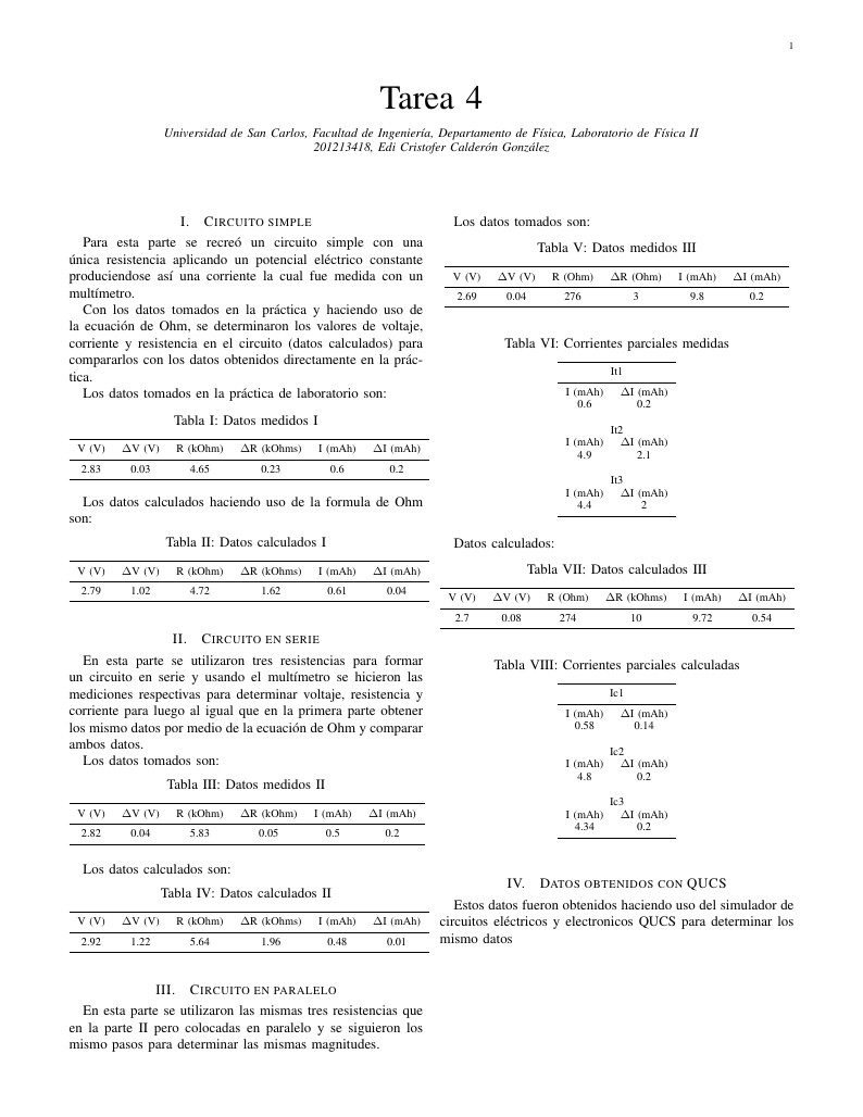
Para esta parte se recreó un circuito simple con una única resistencia aplicando un potencial eléctrico constante produciendose así una corriente la cual fue medida con un multímetro.

Con los datos tomados en la práctica y haciendo uso de la ecuación de Ohm, se determinaron los valores de voltaje, corriente y resistencia en el circuito (datos calculados) para compararlos con los datos obtenidos directamente en la práctica.

Los datos tomados en la práctica de laboratorio son:

\begin{table}[htbp]
  \centering
  \caption{Datos medidos I}
    \begin{tabular}{cccccc}
    \toprule
    V (V) & $\Delta$V (V) & R (kOhm) & $\Delta$R (kOhms) & I (mAh) & $\Delta$I (mAh) \\
    \midrule
    2.83 & 0.03 & 4.65 & 0.23 & 0.6 & 0.2 \\
    \bottomrule
    \end{tabular}%
  \label{tab:addlabel}%
\end{table}%

Los datos calculados haciendo uso de la formula de Ohm son:

\begin{table}[htbp]
  \centering
  \caption{Datos calculados I}
    \begin{tabular}{cccccc}
    \toprule
    V (V) & $\Delta$V (V) & R (kOhm) & $\Delta$R (kOhms) & I (mAh) & $\Delta$I (mAh) \\
    \midrule
    2.79 & 1.02 & 4.72 & 1.62 & 0.61 & 0.04 \\
    \bottomrule
    \end{tabular}%
  \label{tab:addlabel}%
\end{table}%

\section{Circuito en serie}

En esta parte se utilizaron tres resistencias para formar un circuito en serie y usando el multímetro se hicieron las mediciones respectivas para determinar voltaje, resistencia y corriente para luego al igual que en la primera parte obtener los mismo datos por medio de la ecuación de Ohm y comparar ambos datos.

Los datos tomados son:

\begin{table}[htbp]
  \centering
  \caption{Datos medidos II}
    \begin{tabular}{cccccc}
    \toprule
    V (V) & $\Delta$V (V) & R (kOhm) & $\Delta$R (kOhm) & I (mAh) & $\Delta$I (mAh) \\
    \midrule
    2.82 & 0.04 & 5.83 & 0.05 & 0.5  & 0.2 \\
    \bottomrule
    \end{tabular}%
  \label{tab:addlabel}%
\end{table}%


Los datos calculados son:

\begin{table}[htbp]
  \centering
  \caption{Datos calculados II}
    \begin{tabular}{cccccc}
    \toprule
    V (V) & $\Delta$V (V) & R (kOhm) & $\Delta$R (kOhms) & I (mAh) & $\Delta$I (mAh) \\
    \midrule
    2.92 & 1.22 & 5.64 & 1.96 & 0.48 & 0.01 \\
    \bottomrule
    \end{tabular}%
  \label{tab:addlabel}%
\end{table}%

\section{Circuito en paralelo}

En esta parte se utilizaron las mismas tres resistencias que en la parte II pero colocadas en paralelo y se siguieron los mismo pasos para determinar las mismas magnitudes.

\newpage

Los datos tomados son:

\begin{table}[htbp]
  \centering
  \caption{Datos medidos III}
    \begin{tabular}{cccccc}
    \toprule
    V (V) & $\Delta$V (V) & R (Ohm) & $\Delta$R (Ohm) & I (mAh) & $\Delta$I (mAh) \\
    \midrule
    2.69 & 0.04 & 276  & 3    & 9.8  & 0.2 \\
    \bottomrule
    \end{tabular}%
  \label{tab:addlabel}%
\end{table}%

\begin{table}[htbp]
  \centering
  \caption{Corrientes parciales medidas}
    \begin{tabular}{cc}
    \toprule
    \multicolumn{2}{c}{It1} \\
    \midrule
    I (mAh) & $\Delta$I (mAh) \\
    0.6  & 0.2 \\
         &  \\
    \multicolumn{2}{c}{It2} \\
    I (mAh) & $\Delta$I (mAh) \\
    4.9  & 2.1 \\
         &  \\
    \multicolumn{2}{c}{It3} \\
    I (mAh) & $\Delta$I (mAh) \\
    4.4  & 2 \\
    \bottomrule
    \end{tabular}%
  \label{tab:addlabel}%
\end{table}%

Datos calculados:

\begin{table}[htbp]
  \centering
  \caption{Datos calculados III}
    \begin{tabular}{cccccc}
    \toprule
    V (V) & $\Delta$V (V) & R (Ohm) & $\Delta$R (kOhms) & I (mAh) & $\Delta$I (mAh) \\
    \midrule
    2.7  & 0.08 & 274  & 10   & 9.72 & 0.54 \\
    \bottomrule
    \end{tabular}%
  \label{tab:addlabel}%
\end{table}%

\begin{table}[htbp]
  \centering
  \caption{Corrientes parciales calculadas}
    \begin{tabular}{cc}
    \toprule
    \multicolumn{2}{c}{Ic1} \\
    \midrule
    I (mAh) & $\Delta$I (mAh) \\
    0.58 & 0.14 \\
         &  \\
    \multicolumn{2}{c}{Ic2} \\
    I (mAh) & $\Delta$I (mAh) \\
    4.8  & 0.2 \\
         &  \\
    \multicolumn{2}{c}{Ic3} \\
    I (mAh) & $\Delta$I (mAh) \\
    4.34 & 0.2 \\
    \bottomrule
    \end{tabular}%
  \label{tab:addlabel}%
\end{table}%

\section{Datos obtenidos con QUCS}

Estos datos fueron obtenidos haciendo uso del simulador de circuitos eléctricos y electronicos QUCS para determinar los mismo datos

\newpage

\begin{table}[htbp]
  \centering
  \caption{QUCS - Parte I}
    \begin{tabular}{rrrrrr}
    \toprule
    V (V) & $\Delta$V (V) & R (KOhm) & $\Delta$R (Ohm) & I (mAh) & $\Delta$I (mAh) \\
    \midrule
    2.69 & 0   & 4.65 & 0   & 0.606 & 0 \\
    \bottomrule
    \end{tabular}%
  \label{tab:addlabel}%
\end{table}%

\begin{table}[htbp]
  \centering
  \caption{QUCS - Parte II}
    \begin{tabular}{rrrrrr}
    \toprule
    V (V) & $\Delta$V (V) & R (Ohm) & $\Delta$R (Ohm) & I (mAh) & $\Delta$I (mAh) \\
    \midrule
    2.82 & 0   & 0 & 0   & 0.484 & 0 \\
    \bottomrule
    \end{tabular}%
  \label{tab:addlabel}%
\end{table}%


\begin{table}[htbp]
  \centering
  \caption{QUCS - Parte III}
    \begin{tabular}{rrrrrr}
    \toprule
    V (V) & $\Delta$V (V) & R (Ohm) & $\Delta$R (Ohm) & I (mAh) & $\Delta$I (mAh) \\
    \midrule
    2.69 & 0    & 276.67 & 0    & 9.72 & 0 \\
    \bottomrule
    \end{tabular}%
  \label{tab:addlabel}%
\end{table}%


\end{document}